The Build
Hull offset stations and centreline were projected inside the hull and 6mm ply stringers glued, coved and glassed in. Mountings for the aft cockpit bulkhead (to give maximum aft deck length) installed. Transom stiffened and supported.
Stringer grid completed with cockpit aft bulkhead and side tanks installed. Supports for the floor join, hiking stap mountings
and mainsheet block glued and glassed in.
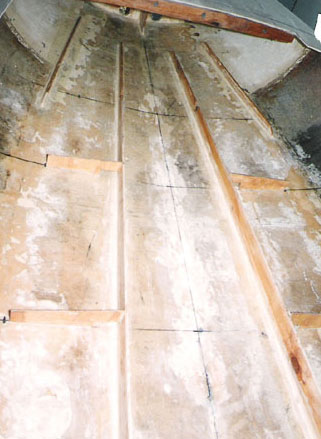
Stringers needed too be this close together to allow the floor to be
made from 6mm plywood. The floor is the heaviest and biggest single piece of construction material. It has to be strong enough to take the
helmsman weight.
Centrecase capping strengthened and lengthened with cedar and carbon fibre.
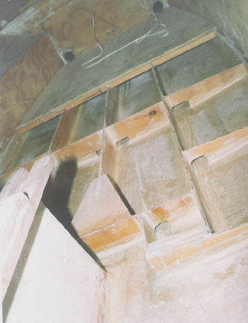
To give maximum stiffness, station 3 and 4 bulkheads were glued, coved and glassed to both the side deck and inside hull. Station 5
bulkheads are fully glassed to make the whole aft end of the boat a
buoyancy tank.
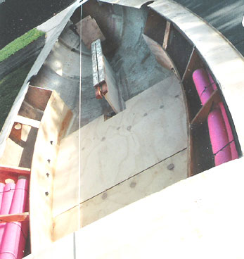
Bundles of closed cell foam rods
(the stuff kids use in swimming pools) were hung in the side tanks to provide positive
buoyancy in case the aft tank is breached.
Foredeck stringers (cedar) installed and glassed to the foam hull stringers. Front centrecase supports go directly to the inside
hull/deck join and hence the gunnel.
Gunnels (not shown) was made from 4 strips of 6mm ply bend around the exterior
deck/hull join and screwed, glued, glassed to form a very stiff, solid foundation for transferring the helmsman righting momentum
into the fordeck.
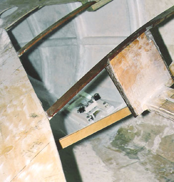
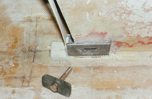
Bottom mast step installed. Adjustment is by 10mm blocks (plus a 5mm one for fine adjustment). Same
thicknesses as the top mast step adjustments. Makes it easy to move the mast forward or backwards in the boat without losing mast
rake (leech tension) settings.
Because of the reduced centreboard arm area as
prescribed in the 2005 rules the centreboard slot position required much mocking up
(in full size cardboard templates) to get it to fit in the centrecase. Centreboard was maximum size.
Too high a centreboard bolt position,
while giving the desirable as close to vertical leading edge, resulted in the top end of the trailing edge chord projecting below the hull. Too low
a centreboard bolt position and the centreboard arm would project below the centrecase capping. With 10mm to play with the best position ended up
being 42mm above the keel.
Even in this position the amount of centreboard above the capping was minimal. Made it difficult to install
a stop plus allow for pulley and bungee cord mountings.
Biggest decision to be made while designing the rebuild was whether to go with the open front
cockpit (Devoti style) or a closed cockpit
one (Vanguard/Lemieux style). Decided on a closed cockpit to keep stiffness in the boat plus save weight.
There doesn't seem to be
a need for a false floor along the centrecase so these were left out to save weight as well.
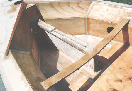
Thwart was fabricated on the curve of
the old traveller from 3 layers of 6mm plywood. Screwed, glued and glassed to the centrecase in maximum aft position with the ends screwed,
glued and glassed to pads on station 4 bulkheads. Thwart acts as a
stressed member of the hull to transfer loads from the helmsman and
centrecase into the boat.
Rebates in the centrecase capping are for plastic inserts that will keep the centreboard in a vertical
position and make lifting and lowering easier by reducing the contact area.
Cockpit coaming was fabricated from cedar.